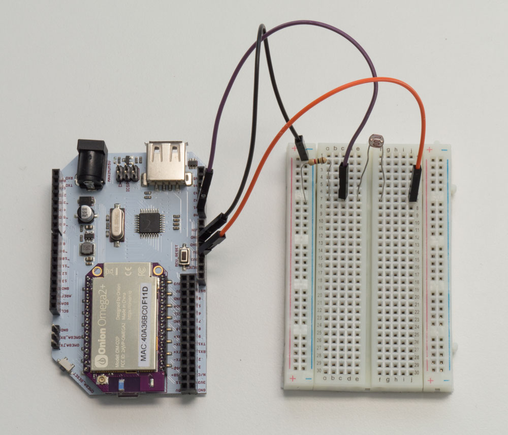

I had to redo all the measurements for the second table when I realized voltage for a one measurement was higher than the one before because I was holding my hand near the flashlight the first time and cast a shadow from the ambient light source. The final table then, showing us how much current was drawn and what the resistance of the photoresistor at each stage was, is as follows… Light Levelīut really, this is a crude method of measuring this – millivolt changes based on sheets of paper stuffed in front of a flashlight in a room with loads of other light and shadow pollution. … we can determine both the current draw of the circuit and the resistance in ohms of the LDR as each light blocker was added, thanks to Ohm’s law and the fact that the same current draw occurs at every node of a voltage divider (more on this in a later post)!įirst, we find the circuit current draw.
#PHOTORESISTOR ARDUINO SERIES#
The value of the series resistor, measured at 987Ω.The voltage drop across the second resistor, the chart above.From the measurements, it also looks like there is a diminishing return on the amount of light blockage you get when you place a sheet of postit note between an LED flashlight and a photo resistor. The voltage input to the circuit as a whole, Vout of my Arduino measured at 4.87V As the amount of available light diminishes, the resistance of the photoresistor increases.You would also expect that as the light decreases, and resistance increases, that the current flowing would decrease as well.

I decided to rerun the test with more blocks so I had more than four data points, and this is what the graph wound up looking like, pretty asymptotic as it approaches the resistance caused by whatever the ambient light is. (analogRead of 512) But if the LDR is hit with a ton of light and is reading. So if the the LDR and the resistor have the same resistance, the 5V is split evenly (2.5V), to each part. With the arduino analogRead, at 5V (its max) it would read 1023, and at 0v it read 0. Remember, this orange multimeter is autoranging, so you’ll have to look closely for the position of the decimal point.Īs the amount of available light diminishes, the resistance of the photoresistor increases. The amount of that 5V that each part gets is proportional to its resistance. So there we go, we have the system setup inside the light box, and ready to start measuring.


 0 kommentar(er)
